
Blog

What Is an Outdoor Light Pole and How Does It Work?

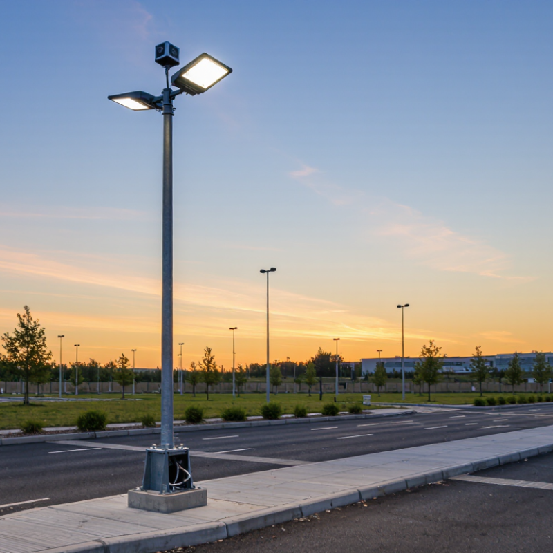
An outdoor light pole is more than a tall metal structure holding a lamp. It is part of a carefully planned lighting system that improves visibility, safety, and nighttime comfort. You may see one beside a roadway, parking area, sports field, or pedestrian path. Its height, material, foundation, and fixture shape all affect performance.

Light Poles Outdoor products usually include a pole shaft, base plate, anchor bolts, wiring, and a mounted luminaire. Electricity travels through protected cables inside the pole. The fixture then converts that electrical energy into directed light. Photocells, timers, or smart controls can switch the system on when daylight fades. Some designs also adjust brightness when fewer people or vehicles are present.

Good design requires more than choosing the tallest pole. Engineers consider wind pressure, soil conditions, corrosion, light distribution, maintenance access, and nearby buildings. A galvanized steel pole may suit a busy roadside, while aluminum can reduce weight in some applications. LED fixtures often provide efficient illumination and long service life. Still, no system is perfect. Poor spacing can create dark patches, glare, or unnecessary light spill. I have found that small installation details often matter as much as the product specification. Regular inspections also reveal loose connections, damaged coatings, or water entry before they become expensive problems. Understanding how a pole works helps property owners, contractors, and planners select lighting that remains dependable after sunset.
What Is an Outdoor Light Pole and How Does It Work?

Definition and Main Functions of an Outdoor Light Pole

An outdoor light pole is a vertical support that carries a luminaire above streets, parking areas, parks, and building entrances. It usually includes a steel or aluminum shaft, base plate, anchor bolts, wiring, and a lighting head. Its main functions are simple but demanding: provide visibility, distribute light across a target area, protect electrical equipment, and withstand wind, rain, vibration, and temperature changes.

The U.S. Department of Energy reports that LED lighting can use at least 75% less energy and last up to 25 times longer than incandescent lighting. These figures explain why LED luminaires are common on modern poles. However, efficiency depends on more than the lamp. Pole height, spacing, beam angle, glare control, and operating schedules shape real performance. A poorly positioned pole can create dark patches or shine into nearby windows. That weakness is often overlooked.

Tips: Check the site plan before choosing pole height. Measure mounting surfaces and soil conditions. Use photocells or scheduled controls to reduce unnecessary operation. The International Energy Agency has identified lighting efficiency and controls as important opportunities for lowering electricity demand. Still, one report cannot replace field testing. Inspect light levels after installation, especially near crossings and corners. A small design error can affect safety. Think beyond brightness. Good outdoor lighting should be useful, controlled, and comfortable for people nearby.

Key Components and Structural Design of Outdoor Light Poles

An outdoor light pole is a vertical support that positions a luminaire above roads, paths, or open areas. Its shaft usually uses galvanized steel, aluminum, or another weather-resistant material. The shaft transfers wind, fixture weight, and vibration toward the foundation. It carries weight. Small details matter.

Key components include the pole shaft, base plate, anchor bolts, handhole, wiring, grounding conductor, and luminaire arm. The base plate connects the shaft to a concrete foundation. Anchor bolts must match the pole’s load and bolt pattern. Inside the shaft, insulated cables deliver power to the fixture. A grounding path helps reduce electrical risk during faults. Drainage and sealed covers also protect internal parts from moisture. A design can look strong and still fail when water collects inside.

Tips: Check the local wind conditions before selecting a pole. Inspect welds, coatings, bolts, and cable access during installation. Keep the foundation level and verify bolt alignment carefully. Field inspections often find small corrosion spots before major damage develops. Reflective surfaces can improve visibility, but excessive brightness may create glare. This balance deserves review, not guesswork.

What Is an Outdoor Light Pole and How Does It Work? - Key Components and Structural Design of Outdoor Light Poles
Component or Design Dimension Primary Function Typical Materials or Specifications How It Works in the Structure Important Design Considerations
Pole Shaft Supports the lighting equipment and transfers vertical and lateral loads toward the foundation. Commonly galvanized steel, aluminum, or reinforced concrete; typical outdoor pole heights range from approximately 3 m to 12 m, depending on the application. The shaft acts as a vertical cantilever. It resists bending caused by wind acting on the pole, luminaire, and accessories. Height, taper, wall thickness, diameter, material strength, and access requirements must be selected for the intended load and site conditions.
Pole Shape and Taper Provides the required strength while controlling material use, weight, and appearance. Typical profiles include round tapered, octagonal tapered, square, and non-tapered cylindrical shafts. A tapered shaft generally places more material near the base, where bending moments are highest, and less material near the top. Uniform geometry can simplify manufacturing, while tapered geometry may improve structural efficiency and visual proportions.
Luminaire or Light Fixture Produces and distributes light over roads, pathways, parking areas, public spaces, or other outdoor locations. Usually an LED fixture with a housing designed for outdoor exposure; common ingress-protection ratings include IP65 or higher for many exterior applications. The fixture is mounted at the top of the pole and creates a concentrated wind area that contributes to the total overturning load. Photometric distribution, light output, glare control, energy use, maintenance access, and fixture weight must match the lighting plan.
Mounting Arm or Bracket Positions the luminaire at the required angle, height, and horizontal outreach. Galvanized steel or aluminum; configurations may include davit arms, straight arms, tenons, wall-style brackets, or outreach arms. The arm transfers the fixture weight and wind force into the pole shaft, often increasing the bending moment at the pole base. Arm length, mounting angle, connection strength, vibration resistance, and compatibility with the luminaire must be checked.
Top Tenon or Mounting Adapter Creates the mechanical connection between the pole and a fixture or mounting arm. Steel or aluminum adapter sized to the fixture mounting socket; dimensions vary by luminaire design. Clamping bolts or fasteners secure the fixture while the adapter transfers gravity and wind loads into the shaft. The connection should prevent rotation and provide adequate corrosion resistance, thread engagement, and fastener preload.
Base Plate and Anchor Bolts Connects a base-mounted pole to the concrete foundation and resists uplift, shear, and overturning forces. Steel base plate with multiple anchor bolts, nuts, and washers; bolt size and arrangement are determined by structural calculations. Wind-induced bending creates tension in some anchor bolts and compression between the base plate and foundation. Base-plate thickness, bolt circle, weld quality, leveling method, grout, bolt corrosion protection, and installation tolerances are critical.
Foundation Transfers the pole loads safely into the surrounding soil. Usually reinforced concrete with embedded anchor bolts or a foundation cage; dimensions depend on soil and loading conditions. The foundation resists overturning through its own weight, soil pressure, reinforcement, and the stiffness of the embedded connection. Soil bearing capacity, frost depth, groundwater, drainage, concrete strength, reinforcement, and local construction requirements must be evaluated.
Handhole and Access Door Provides access to wiring, terminals, fuses, grounding connections, and maintenance components inside the pole. Lockable metal access door with a gasket or weather-resistant closure; often located near the lower section of the shaft. The opening allows electrical servicing but locally changes the shaft geometry and must be reinforced or designed for the resulting stress concentration. The door should be secure, corrosion-resistant, properly sealed, and large enough for safe maintenance without weakening the pole.
Internal Electrical Cable Carries electrical power from the underground supply or service connection to the luminaire. Outdoor-rated insulated conductors selected for voltage, current, temperature, moisture exposure, and local electrical requirements. Cables run through the hollow shaft and connect to terminals, protective devices, and the fixture. Cable size, insulation rating, voltage drop, bend radius, strain relief, and separation from sharp metal edges must be considered.
Terminal Block or Fuse Unit Provides a serviceable connection point and may protect the luminaire circuit from overcurrent. Weather-resistant terminal assembly with appropriately rated terminals, fuses, or circuit protection equipment. The unit distributes incoming power to the fixture and allows the circuit to be isolated during maintenance. Ratings must match the supply voltage and load. Components should be accessible, securely mounted, and protected from moisture and contamination.
Grounding and Bonding System Provides a low-resistance path for fault current and helps reduce electric shock risk. Grounding conductor, bonding hardware, grounding lug, and a connection to the equipment grounding system required by the applicable electrical code. If an insulation fault energizes the metal pole, the grounding path helps conduct fault current so protective equipment can disconnect the supply. All conductive parts should be bonded as required. Connections need protection against loosening, corrosion, and accidental disconnection.
Protective Coating Reduces corrosion caused by rain, humidity, salt, pollutants, and soil contact. Hot-dip galvanized steel, powder-coated aluminum, paint systems, or compatible multi-layer corrosion-protection systems. The coating separates the structural metal from the environment and extends service life when surface preparation and coverage are adequate. Coating selection should reflect climate, coastal exposure, abrasion risk, drainage details, cut edges, weld areas, and maintenance practices.
Wind Load Design Ensures the pole remains stable and structurally adequate during site-specific wind events. Design inputs include basic wind speed, exposure category, gust factors, projected area, drag effects, fixture weight, and accessory loads. Wind pressure produces shear and bending moment along the shaft, with the greatest overturning demand generally occurring near the base. Structural design should follow the applicable local code or recognized standard and account for the complete pole-and-fixture assembly.
Vibration and Fatigue Resistance Limits damage caused by repeated wind-induced movement, traffic vibration, or equipment operation. Determined through shaft stiffness, natural frequency, connection detailing, damping, and fatigue-resistant weld design. Repeated cycles of stress can accumulate over time even when individual wind events do not exceed the maximum static design load. Long arms, large fixtures, exposed locations, and flexible poles may require additional vibration or fatigue assessment.
Maintenance and Service Life Preserves lighting performance, electrical safety, structural integrity, and operating reliability. Routine inspection may include coating condition, bolts, welds, anchor areas, access doors, wiring, grounding, and fixture operation. Periodic inspection identifies corrosion, cracking, loose connections, water ingress, foundation movement, and other conditions before failure occurs. Inspection frequency should reflect climate, traffic exposure, coastal conditions, pole age, and the consequences of failure.

How an Outdoor Light Pole Produces and Directs Light

An outdoor light pole supports a luminaire and helps place light where people need it. Inside the luminaire, an electrical driver converts incoming AC power into controlled current. That current energizes LED chips, which produce visible light through electroluminescence. The U.S. Department of Energy’s 2023 Solid-State Lighting R&D Opportunities report notes that LED packages can exceed 200 lumens per watt under laboratory conditions. Real fixtures usually deliver less because lenses, wiring, and heat reduce performance.

The light is not simply thrown downward. Reflectors, lenses, and shields shape the beam into a chosen photometric distribution. IES TM-15 classifications help engineers compare these distributions. A narrow pattern can reach a roadway, while a wider pattern can brighten a pedestrian area. Pole height, arm length, spacing, and tilt then affect illuminance and uniformity. IES RP-8-22 treats these measurements as important roadway-lighting design factors. Photocells and dimming controls can reduce output during low-use hours. Good control matters.

Small errors remain costly. A few degrees of tilt may send light toward windows or the sky. CIE 150:2017 addresses obtrusive light and recommends limiting unwanted upward and sideways emissions. Yet calculations cannot predict every tree, wet surface, or seasonal obstruction. Field measurements and nighttime review are still necessary.

Power Supply, Controls, and Lighting Operation

What Is an Outdoor Light Pole and How Does It Work?

An outdoor light pole is more than a metal support for a lamp. It combines structure, wiring, controls, and a lighting fixture. In field inspections, I usually check the base first. A loose access cover or wet conduit can create trouble before the lamp fails. Power normally travels from a distribution panel through underground conduit. A circuit breaker protects the branch circuit from excessive current. Proper grounding gives fault current a safer path.

The control system decides when the light operates. A photocell turns the fixture on at dusk and off at daylight. A timer can follow scheduled hours, while motion sensors increase brightness when people approach. Some installations use low-voltage control wiring or wireless signals. The lighting driver then changes incoming power into the stable current required by the LED module. This process supports consistent brightness and reduces energy waste.

Small details matter. A technician should test voltage, inspect connections, and confirm that the pole remains level. Water inside the base can corrode terminals silently. A surge protector may help during unstable weather, but it cannot replace sound grounding. I once found a light operating normally with a badly damaged conduit seal. It looked safe from a distance. That experience changed my inspection habits. Controls also need adjustment; an overly sensitive sensor can cause constant switching, shorten component life, and annoy nearby residents. Not every dimming problem comes from the lamp.

Common Types, Applications, and Maintenance Requirements

An outdoor light pole is a vertical support that holds a lighting fixture above roads, walkways, parking areas, or public spaces. It usually includes a steel, aluminum, or concrete shaft, a base plate, anchor bolts, wiring, and a luminaire. A photocell, timer, or control system switches the light on when daylight fades. The pole itself does not create light. It safely positions and protects the electrical equipment.

Common types include straight poles, tapered poles, decorative poles, high-mast structures, and solar-powered poles. Steel models suit highways and large parking areas because they handle heavy fixtures and strong wind. Aluminum poles resist corrosion and weigh less. Decorative designs often serve parks, campuses, and commercial entrances. Solar poles work well in remote locations, although shaded panels and cloudy weather can reduce performance. One choice rarely fits every site.

Maintenance should begin with a visual inspection. Look for rust, cracks, leaning, damaged wiring, loose bolts, and water inside the base. Check the grounding connection and inspect cable insulation during scheduled electrical testing. Clean lenses and solar panels when dust, insects, or bird deposits reduce light output. After severe wind, flooding, or impact, isolate the area and arrange a professional inspection. In practice, maintenance plans are sometimes too general. Local wind exposure, soil movement, and salt air require different inspection intervals. Follow applicable electrical and structural codes, and keep dated service records. Small defects become expensive failures.

Go to Top