

What Are the Top Intelligent Pole Types in 2026?
By 2026, an Intelligent Pole can combine street lighting, wireless connectivity, environmental sensors, cameras, and public charging. The best choice depends on local needs, not the number of devices attached. A busy transport corridor may benefit from a communications-focused pole, while a park may need efficient lighting and air-quality monitoring.
The GSMA’s Mobile Economy 2024 report counted 1.6 billion 5G connections worldwide at the end of 2023. It projects 5.5 billion by 2030. That growth increases demand for well-placed network infrastructure. The IEA’s Electricity 2024 report also forecasts global electricity demand growth averaging about 3.4% annually from 2024 to 2026. Energy use matters. Efficient lighting, power management, and carefully planned charging can help cities manage operating costs. These figures describe wider infrastructure trends, not guaranteed returns from any pole deployment.
This guide compares leading types: smart-lighting poles, 5G small-cell poles, sensing and monitoring poles, security-enabled poles, EV-charging poles, and integrated multifunctional models. Their capabilities vary. Some support modular upgrades; others suit a single, specific function. Cities should check site conditions, connectivity, maintenance access, data protection, and lifecycle costs before choosing. A camera or sensor also needs a clear purpose and responsible data handling. Not every site needs every feature. That is easy to forget when technology looks impressive. The strongest option is usually the one that solves a measured local problem and can be maintained reliably.
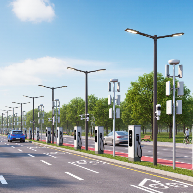
5G Connectivity Poles: Compare 3GPP NR Bands from FR1 (≤7.125 GHz) to FR2 (≤71 GHz)
In 2026, an intelligent pole’s 5G role depends less on its shape than on the 3GPP NR spectrum it must support. FR1 extends up to 7.125 GHz, and sub-6 GHz channels often provide broader coverage and better building penetration. A pole beside a bus stop may host compact radios, antennas, fiber backhaul, and power monitoring. Space is still limited.
FR2 covers selected NR bands from 24.25 GHz through 71 GHz, not every frequency in between. These higher bands can deliver substantial capacity in busy plazas, but signals travel shorter distances and are more easily blocked by walls, buses, and tree canopies. Small cells may need closer spacing. Millimeter-wave antennas also require careful alignment and a clear installation path.
Pole selection should match local spectrum, expected traffic, and site conditions. Check radio compatibility, power capacity, thermal management, wind loading, and maintenance access before installation. A tidy coverage model can still be wrong: foliage growth, heat, cable routing, and nearby construction may change field results. That deserves a second look.
What Are the Top Intelligent Pole Types in 2026? — 5G Connectivity Poles: Compare 3GPP NR Bands from FR1 (≤7.125 GHz) to FR2 (≤71 GHz)
| Intelligent Pole Type | 3GPP NR Frequency Range | Illustrative NR Band Examples | Typical Radio and Antenna Arrangement | Coverage and Capacity Characteristics | Typical Deployment Fit | Key Design Considerations |
|---|---|---|---|---|---|---|
| FR1 wide-area coverage pole | FR1: 410 MHz–7.125 GHz | n28: 703–803 MHz; n78: 3.3–3.8 GHz | FR1 radio equipment connected to pole-mounted panel or compact antenna systems. | Lower FR1 frequencies generally provide broader coverage and better building penetration than FR2, subject to frequency, terrain, antenna, and deployment conditions. | Road corridors, residential areas, and sites needing broad outdoor coverage. | Check local spectrum allocation, antenna separation, radio power, structural loading, and access for maintenance. |
| FR1 capacity-focused street pole | FR1: 410 MHz–7.125 GHz | n77: 3.3–4.2 GHz; n78: 3.3–3.8 GHz | Compact mid-band radio with a multi-element antenna; configuration depends on the network and local regulations. | Mid-band spectrum can provide more capacity than many lower-frequency deployments, while generally covering less distance than lower-band FR1. | Busy streets, transit stops, and mixed-use districts where coverage and capacity are both required. | Actual bandwidth and performance depend on the licensed channel, network configuration, interference, and surrounding clutter. |
| FR1 + FR2 layered-coverage pole | FR1: 410 MHz–7.125 GHz; FR2-1: 24.25–52.6 GHz; FR2-2: 52.6–71 GHz | FR1 examples: n28, n78. FR2-1 examples: n258 (24.25–27.5 GHz), n257 (26.5–29.5 GHz). | Separate FR1 and FR2 radio/antenna systems on one pole, where supported by the network design. | FR1 can provide a wider-area coverage layer; FR2 can add localized capacity. FR2 links are more sensitive to blockage and typically serve smaller areas. | High-demand urban locations where broad-area service and targeted hotspot capacity are both needed. | Plan for antenna placement, mutual interference, power and fiber availability, cooling, wind loading, and safe servicing. |
| FR2 millimeter-wave small-cell pole | FR2-1: 24.25–52.6 GHz; FR2-2: 52.6–71 GHz | n257: 26.5–29.5 GHz; n258: 24.25–27.5 GHz; n260: 37–40 GHz | Compact FR2 radio with an integrated or closely coupled directional antenna array. | Can support high-capacity, localized coverage where suitable spectrum and equipment are deployed; range and reliability are affected by blockage and propagation conditions. | Dense public spaces, venues, transport hubs, and other targeted hotspots. | Carefully assess line of sight, mounting direction, nearby obstructions, site density, backhaul, and country-specific band availability. |
| FR2-2 higher-frequency hotspot pole | FR2-2: 52.6–71 GHz | 3GPP FR2-2 frequency range; specific NR band support and commercial availability depend on the applicable specification release and market. | Purpose-designed FR2 radio and antenna hardware matched to the selected NR band. | Higher-frequency links require careful attention to path loss, blockage, and propagation; deployment suitability is highly site- and equipment-dependent. | Specialized, short-range capacity zones where compatible spectrum and equipment are available. | Verify supported NR bands, local authorization, device ecosystem, link budget, and environmental performance before selection. |
3GPP range reference: FR1 is 410 MHz–7.125 GHz; FR2-1 is 24.25–52.6 GHz; and FR2-2 is 52.6–71 GHz. The interval from 7.125 GHz to 24.25 GHz is outside these defined FR1 and FR2 ranges. NR band availability, permitted spectrum, and supported equipment vary by country and specification release. Pole configurations are deployment archetypes, not standardized 3GPP pole categories.

About Us
We serve the Greater Milwaukee area: Waukesha, Milwaukee, Washington, Ozaukee Counties and nearby areas, including Germantown, Menomonee Falls, Mequon, Cedarburg, Thiensville, Grafton, Jackson, West Bend, Hartland, Waukesha, Brookfield, West Allis, Franklin, Greenfield and more. We are Wisconsin’s Best Contractor for Replacement Windows, Doors, Siding & Roofing!
Contact Details
Address:
N112 W14880 Mequon Road
Germantown, Wisconsin 53022
Phone:
Email:
Showroom Hours
Monday: 9am – 5pm
Tuesday: 9am – 5pm
Wednesday: 9am – 5pm
Thursday: 9am – 5pm
Friday: 9am – 4:30 pm
Saturday by Appointment
Evenings by Appointment
Directions
© 2023 All American Window & Door | Sitemap